What Does Wedge Barriers Do?
In the following discussion, recommendation is made to a surface of a structure to which the wedge-style obstacle is installed. In the detailed embodiments, the upper side of the support is significantly flush with the surface of the structure. In such personifications, the wedge-style barrier may be mounted straight to the surface area of the structure. In other personifications, the top side of the anchor might be a little increased above the surface of the structure or somewhat recessed below the surface area of the foundation. 1 is a front viewpoint sight of a personification of a surface-mounted wedge-style obstacle 10. As revealed, the barrier 10 is mounted to a surface 12 of a structure 14(e. g., a shallow structure ). The foundation
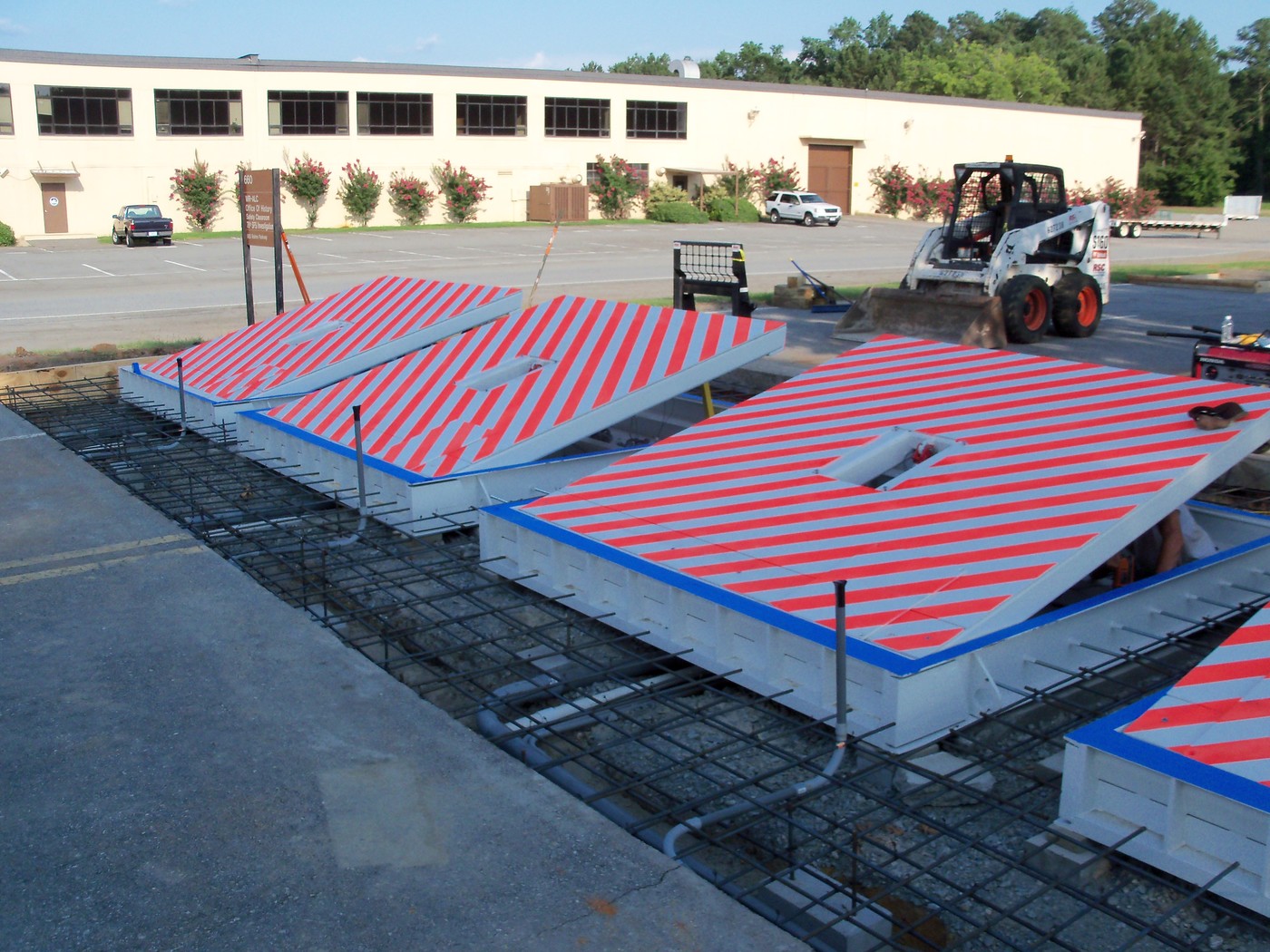
14 and the surface 12 to which the barrier 10 obstacle secured may be made from concrete. 2, the barrier 10 is placed to or includes an anchor or subframe (e. g., support 30 received FIG. 2 )secured underneath the surface area 12. For instance, the bather 10 might be bolted to the anchor or protected to the anchor by other mechanical fasteners. In the illustrated embodiment, the barrier 10 includes a wedge plate 16, that includes a section that is significantly parallel with the surface area 12 when the obstacle 10 is in the pulled back position. Simply put, cars or people may overlook the obstacle 10 when the obstacle 10 is in the retracted position and experience slight altitude family member to the surface 12 while on the barrier 10. As talked about carefully below, when the barrier 10 is in the deployed placement, the wedge plate 16 is held and sustained in an increased placement by a training mechanism of the obstacle 10. Additionally, the elements 18 might be bolted or otherwise mechanically coupled to one another. In this way, repair work or replacement of one or even more components 18 might be streamlined and streamlined. That is, fixing or substitute of single components
18 might be done faster, conveniently, and expense successfully. FIG. In specific embodiments, the support 30 may be a steel frame including plates, beam of lights(e. g., I-beams ), and/or other structures that are safeguarded within the structure 14, which might be concrete. At the surface area 12, a top side 28 of the anchor 30 may go to least partly subjected
, consequently enabling the attachment of the barrier 10 to the support 30. g., threaded openings)in several light beams or plates of the anchor 30 might be exposed to the surface area 12. In this manner, screws 32 or other mechanical fasteners might be made use of to secure the obstacle 10 to the anchor 30. As the obstacle 10 is placed to the surface area 12 of the structure 14, collection of debris and various other material below the obstacle might be decreased, and components of the bather 10 may not be exposed to below grade settings. As suggested by reference numeral 52, the lifting system 50 includes elements disposed under the wedge plate 16. As an example, the elements 52 below the wedge plate 16 might consist of an electromechanical actuator, a cam, several web cam surfaces, and so forth. In addition, the lifting device 50 includes a spring assembly 54
The springtime rod 58 is paired to a webcam(e. g., camera 80 displayed in FIG. 4) of the lifting mechanism 50. The springtimes 60 disposed concerning the springtime pole 58 are kept in compression by springtime supports 62, including a taken care of spring support 64. That is, the set spring support 64 is dealt with loved one to the foundation 14 and the rest of the bather 10.
Top Guidelines Of Wedge Barriers
The staying pressure used to
the cam camera deploy the wedge plate 16 may be provided given an electromechanical actuator 84 or other various other. The spring assembly 54 and the actuator 84(e. Wedge Barriers. g., electromechanical actuator)may operate together to equate the camera and lift the wedge plate 16.
As pointed out above, the spring assembly 54 applies a consistent force on the web cam, while the electromechanical actuator might be managed to put in a variable pressure on the camera, thereby allowing the training and reducing( i. e., deploying and pulling back )of the wedge plate 16. In specific their explanation embodiments, the constant pressure applied by the spring assembly 54 might be adjustable. g., electromechanical actuator) is impaired. As will certainly be appreciated, the springtime assembly 54 might be covered and protected from particles or various other aspects by a cover plate(e. g., cover plate 68 shown in FIG. 4) that might be significantly flush with the raised surface 38 of the foundation 14. As pointed out above, in the deployed placement, the wedge plate 16 serves to block gain access to or traveling past the obstacle 10. For instance, the obstacle 10(e. g., the wedge plate 16 )might block pedestrians or lorries from accessing a residential or commercial property or pathway. As discussed above, the obstacle 10 is affixed to the anchor 30 secured within the structure 14,

front brackets 71. Consequently, the affiliation settings up 72 might pivot and turn to enable the collapse and extension of the affiliation assemblies 72 throughout retraction and implementation of the bather 10. The link assemblies 72 cause movement of the wedge plate 16 to be restricted. If an automobile is taking a trip in the direction of the deployed wedge plate 16(e. For example, in one situation, the safety and security legs 86 might be extended duringmaintenance of the barrier 10. When the safety legs 86 are deployed, the security legs 86 sustain the weight of the wedge plate 16 against the surface 12. As an outcome, the lifting system 50 may be deactivated, serviced, eliminated, look at this web-site changed, and so forth. FIG. 5 is partial viewpoint view of a personification of the surface-mounted wedge-style obstacle 10, highlighting the web cam 80 and the webcam surfaces 82 of the lifting mechanism 50. Specifically, two cam surface areas 82, which are described as reduced web cam surface areas 83, are positioned below the cam 80. The reduced web cam surfaces 83 may be repaired to the surface 12 (e. For instance, the lower camera surface areas 83 and the installing plate 85 might form a solitary item that is safeguarded to next page the support 30 by screws or various other mechanical bolts. Furthermore, 2 webcam surface areas 82, which are described as top camera surface areas 87, are positioned above the camera 80 and paired to (e. In various other personifications, interfering layers or plates might be placed in between the surface area 12 and the reduced camera surface areas 83 and/or the wedge plate 16 and the top webcam surfaces 87 As pointed out above, the camera
80 converts along the camera surface areas 82 when the wedge plate 16 is lifted from the withdrawed position to the deployed placement. Additionally, as mentioned over, the springtime assembly 54 (see FIG. 3 )may provide a force acting upon the web cam 80 in the instructions 102 by means of spring rod 58, which might decrease the pressure the electromechanical actuator 84 is needed to use to the webcam 80 in order to activate and raise the wedge plate 16. 1 )to the released placement(see FIG. 4). As shown, the webcam 80 consists of track wheels 104(e. g., rollers), which call and equate along the cam surface areas 82 during procedure.
Comments on “The Of Wedge Barriers”